How to Polar Align a Star Tracker

How to Polar Align a Star Tracker
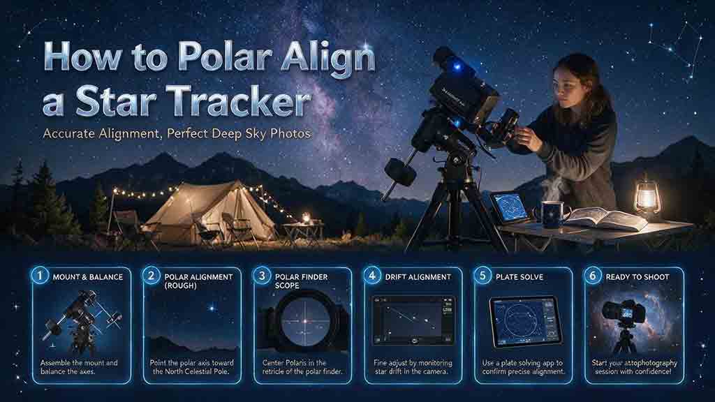
To polar align a star tracker, place it on stable ground, aim its right-ascension axis toward the correct celestial pole, set the wedge near your local latitude, and refine the position with the tracker’s polar scope, reticle app, electronic polar camera, or plate-solving tool. Lock the adjustments, frame the subject without moving the tripod, then verify alignment with a test exposure and correct any remaining drift.
Key Takeaways
- Polar alignment means pointing the tracker’s right-ascension axis, not the camera lens or tripod head, toward the north or south celestial pole.
- Polaris is close to the north celestial pole but is not exactly on it; use the correct reticle position for the date, time, and location.
- Southern Hemisphere users normally align with the Octans region, Sigma Octantis, or a plate-solving method because no bright star marks the south celestial pole.
- Leveling the tripod is helpful because it makes altitude and azimuth adjustments more predictable, but leveling alone does not create polar alignment.
- Recheck alignment after loading, balancing, framing, or tightening the system because those actions can shift a lightweight tracker.
This guide covers rough alignment, optical polar scopes, reticle apps, electronic polar cameras, plate-solving routines, obstructed-pole situations, exposure verification, and common faults. It also provides a three-pass workflow, a method-selection table, Northern and Southern Hemisphere instructions, a field checklist, practical scenarios, and a detailed troubleshooting section.
Method note: This guide is based on current manufacturer manuals, NASA sky-reference information, NOAA magnetic-declination guidance, and official polar-alignment software documentation rather than hands-on testing of every tracker. Reticles, apps, adjustment directions, payload procedures, and software requirements vary by model.
What Does Polar Alignment Actually Do?
Polar alignment makes the tracker’s right-ascension axis parallel, as closely as practical, to Earth’s rotational axis.
A star tracker rotates around its right-ascension axis at a selected celestial rate to counter the apparent movement of the sky. When the axis points away from the celestial pole, stars drift across the frame and may rotate around the guide target during longer captures.
Which Part of the Tracker Must Point at the Pole?
The right-ascension axis, usually shortened to RA axis, must point at the celestial pole.
Do not align:
- The camera lens.
- The ball head.
- The tripod’s center column.
- The counterweight shaft unless the manufacturer identifies it as parallel to the RA axis.
- A decorative arrow that is not documented as an alignment reference.
An optical polar scope is normally installed along or parallel to the RA axis. An electronic polar camera also needs a known relationship to that axis.
Is Polar Alignment the Same as Star Alignment?
No.
| Procedure | Purpose |
|---|---|
| Polar alignment | Points the RA axis toward the celestial pole for tracking |
| One-, two-, or three-star alignment | Builds a pointing model so a GoTo mount can locate objects |
| Plate solving | Identifies where a camera is pointed by matching star patterns |
| Autoguiding | Measures tracking error during an exposure and sends corrections |
| Balancing | Distributes payload weight so the drive works consistently |
A GoTo alignment does not automatically correct a poor mechanical polar alignment. Autoguiding can reduce some tracking error, but it does not make large polar error harmless and cannot remove all field rotation.
How Accurate Does a Star Tracker Need to Be?
The required accuracy depends on the image rather than on one universal number.
More demanding situations include:
- Longer exposure time.
- Longer focal length.
- Smaller camera pixels.
- Large prints or heavy cropping.
- Multi-hour sequences.
- Targets near the celestial equator.
- Panoramas that require consistent star shape.
- Unguided deep-sky imaging.
Less demanding situations include:
- Short exposures.
- Very wide lenses.
- Small online output.
- Intentional star trails.
- Landscape sequences where the sky is stacked from many short frames.
A rough alignment may be sufficient for a short wide-angle exposure, while a long-lens deep-sky sequence may require plate-solving or drift verification.
What Polar Alignment Cannot Fix
A precise alignment does not correct:
- Periodic error in the tracker’s drive.
- Wind or tripod vibration.
- Loose clamps.
- Poor balance.
- Flexure.
- Incorrect tracking rate.
- Lens or telescope aberrations.
- Missed focus.
- A shutter time that exceeds the system’s real tracking capability.
If star elongation remains after good polar alignment, investigate the complete mechanical and optical system.
What Equipment Do You Need?
The required tools depend on the alignment method.
Basic Equipment
- Stable tripod.
- Star tracker.
- Equatorial wedge or altitude-azimuth base.
- Camera mounting system.
- Counterweight and declination bracket when required.
- Red light with adjustable brightness.
- Phone with location and time set correctly.
- Tracker manual.
- Test camera and lens.
- Spare battery or power source.
Method-Specific Tools
| Method | Additional equipment | Best fit |
|---|---|---|
| Rough compass and latitude | Compass or map and latitude source | Initial setup and short wide-angle exposures |
| Optical polar scope | Built-in or attached polar scope and illuminator | Portable trackers with a clear pole view |
| Reticle app | Model-compatible polar-scope app | Correct placement of Polaris or Octans stars |
| Electronic polar camera | Compatible computer, phone, or controller | Fast repeatable alignment and difficult visual conditions |
| Plate-solving alignment | Supported camera, software, and usable field near the pole | Longer lenses and automated setups |
| Drift alignment | Imaging camera or reticle view and sufficient time | Pole blocked or high-accuracy verification |
Do not assume that an app supports every reticle. The circle orientation, clock scale, epoch marks, and hemisphere layout are model-specific.
How Do You Prepare the Tracker Safely?
Complete the mechanical setup before fine alignment whenever the tracker design allows it.
Step 1: Choose Stable Ground
Use firm, level-enough ground that will not settle during the session.
Avoid:
- Loose sand.
- Soft mud.
- A flexible deck.
- A roadway or trail.
- A cliff edge.
- A surface disturbed by foot traffic.
- Fully extended center columns when they reduce stability.
Spread the tripod legs securely and confirm that all locks are engaged.
Step 2: Level the Tripod
Leveling is not the astronomical goal, but it improves the setup workflow.
A level base helps:
- The wedge latitude scale provide a useful starting point.
- Altitude adjustments remain mostly vertical.
- Azimuth adjustments remain mostly horizontal.
- The tracker avoid running out of adjustment travel unexpectedly.
A perfectly level tripod cannot compensate for an RA axis that points away from the pole.
Step 3: Install the Wedge and Tracker
Attach the wedge or altitude-azimuth base tightly enough to prevent movement. Leave the fine-adjustment controls usable.
Confirm:
- The tracker cannot rotate on the tripod plate.
- The wedge is installed in the correct orientation.
- Adjustment bolts are not at the end of their travel.
- The polar-scope path is unobstructed.
- Cables will not pull during RA rotation.
Step 4: Install and Balance the Payload
Follow the manufacturer’s sequence for the counterweight, camera, lens, telescope, and declination bracket.
Sky-Watcher’s Star Adventurer GTi manual instructs users to balance the RA and declination axes and warns that the equipment must be securely attached to a stable tripod before polar alignment and operation. (inter-static.skywatcher.com)
A lightweight tracker may shift when a heavy camera is added. If the polar scope becomes blocked by the payload, complete the manufacturer’s required early alignment steps, install the camera carefully, and recheck through another method when possible.
What Is the Three-Pass Polar Alignment Method?
The three-pass method separates setup into coarse positioning, precise alignment, and real-image verification.
Pass 1: Point the RA Axis in the Correct General Direction
In the Northern Hemisphere, point the RA axis toward true north.
In the Southern Hemisphere, point it toward true south.
A magnetic compass is only a rough guide because it points toward magnetic north rather than true north. NOAA defines magnetic declination as the angle between magnetic north and true north and notes that the value changes with location and time. (ncei.noaa.gov)
Keep a phone compass away from:
- The tracker motor.
- Counterweights.
- Steel tripod parts.
- Vehicles.
- Power banks.
- Speakers.
- Magnetic clasps.
Use a map, known landmark, or corrected compass bearing when possible.
Pass 2: Set the Approximate Polar Altitude
Set the wedge altitude near the absolute value of the observing latitude.
Example:
- At 35° north latitude, start near 35° above the true northern horizon.
- At 35° south latitude, start near 35° above the true southern horizon.
NASA explains that the altitude of Polaris above the northern horizon provides a close approximation of the observer’s latitude because Polaris lies close to the north celestial pole. (NASA Science)
The wedge scale is only a starting point. Tripod leveling, scale accuracy, mechanical play, and manufacturing tolerances can introduce error.
Pass 3: Refine and Verify
Refine the RA axis with one of these methods:
- Optical polar scope and reticle.
- Electronic polar camera.
- Plate-solving routine.
- Drift alignment.
Then frame the target carefully and take a tracked test exposure. Recheck if the tripod, wedge, tracker, or payload moves.
How Do You Polar Align in the Northern Hemisphere?
Use Polaris to locate the polar region, then place Polaris at the correct position on the tracker’s reticle or software display.
NASA describes Polaris as being close to, but not exactly at, the north celestial pole. (NASA Science) Centering Polaris blindly can therefore leave a noticeable alignment error.
Step-by-Step Optical Polar-Scope Method
- Set up, level, load, and balance the tracker as required.
- Point the RA axis roughly toward true north.
- Set the wedge near the local latitude.
- Remove the polar-scope cap.
- Turn on the illuminator at the lowest usable brightness.
- Rotate the RA axis if required to open the polar-scope sight path.
- Confirm that the bright star in view is Polaris.
- Open the tracker-compatible reticle app or calculate the documented clock position.
- Match the reticle’s required orientation.
- Use only the wedge altitude and azimuth adjusters to move Polaris to the indicated location.
- Tighten locks gradually while watching for movement.
- Recheck the position after framing the camera.
Do not move Polaris into place with the camera ball head or declination control. Those adjustments change framing, not the RA-axis direction.
How Do You Confirm That the Star Is Polaris?
Use the Big Dipper or Cassiopeia as a guide, or compare the field with a planetarium app.
NASA’s guide to finding Polaris uses the two outer stars of the Big Dipper’s bowl as pointers toward the North Star. (NASA Science)
A polar scope may show several stars. Confirm the pattern rather than selecting the first bright point.
How Do You Polar Align in the Southern Hemisphere?
Southern polar alignment is more difficult visually because no bright star sits near the south celestial pole.
A polar scope may use a small pattern of stars in Octans. Sky-Watcher’s Star Adventurer GTi manual instructs Southern Hemisphere users to orient the Octans drawing to four dim stars and move those stars into the reticle’s marked circles with the wedge adjustments. (inter-static.skywatcher.com)
Step-by-Step Southern Optical Method
- Point the RA axis roughly toward true south.
- Set the wedge near the absolute value of the local latitude.
- Use a planetarium app or star chart to identify the Octans region.
- Allow enough dark adaptation to see the faint reference stars.
- Dim the polar-scope illuminator so it does not hide the stars.
- Rotate the RA axis or reticle orientation as the manual requires.
- Match the observed Octans pattern to the reticle.
- Use the altitude and azimuth controls to place the stars in the marked positions.
- Lock the wedge gradually.
- Verify with a tracked exposure or software routine.
The exact pattern and reticle marks vary. Do not substitute a Northern Hemisphere clock-position method unless the tracker manual explicitly supports it.
What If You Cannot See the Octans Pattern?
Use:
- An electronic polar camera.
- Plate-solving polar alignment.
- A documented no-pole routine.
- Drift alignment.
A dim polar illuminator, binoculars used only for identifying the region, and a dark-adapted eye may help, but software is often more reliable from light-polluted locations.
How Do You Use a Polar-Scope App Correctly?
A polar-scope app calculates where a pole reference star should appear on a specific reticle at the selected time and location.
Before relying on it, confirm:
- Correct tracker or reticle model.
- Correct hemisphere.
- Correct time.
- Correct time zone.
- Correct daylight-saving setting when required.
- Correct location.
- Whether the view is displayed as seen through the scope or as a normal sky view.
- Whether the reticle must be physically leveled or rotated.
iOptron directs SkyGuider Pro users to model-specific polar-scope apps for determining where to place the pole star on the reticle. (ioptron.com)
Common App Orientation Error
Some app diagrams reproduce the inverted or rotated view through the polar scope. Others show the sky in a normal upright orientation.
Read the legend before moving the mount. A mirrored or reversed interpretation can place Polaris on the wrong side of the reticle even when the clock number appears correct.
How Do You Use an Electronic Polar Camera?
An electronic polar camera captures the pole region, identifies stars, determines the RA-axis direction, and guides altitude and azimuth adjustment.
iOptron’s iPolar uses plate solving and on-screen instructions and is designed to work without requiring the pole star itself to be visible, although the camera still needs a usable polar-region star field. (ioptron.com)
General Electronic Alignment Workflow
- Install the polar camera in its calibrated position.
- Connect the required power and data cable.
- Open the current supported software.
- Enter or confirm the location.
- Point the tracker roughly toward the pole.
- Capture or allow the software to identify the star field.
- Follow the documented rotation or calibration step.
- Adjust only the wedge altitude and azimuth controls.
- Stop when the error is appropriate for the planned image.
- Lock and verify that the result does not shift.
Check current operating-system support before traveling. A camera that requires a laptop or particular driver changes the field workflow.
How Does Plate-Solving Polar Alignment Work?
A plate-solving routine identifies star patterns in two or more images and compares the camera’s apparent rotation center with the true celestial pole.
SharpCap’s current polar-alignment routine:
- Captures one field near the pole.
- Rotates the mount about 90° around the RA axis.
- Captures a second field.
- Plate-solves both fields.
- Determines where the RA axis points.
- Provides live altitude and azimuth guidance. (docs.sharpcap.co.uk)
SharpCap documents several requirements, including a supported camera, an equatorial mount, a suitable field of view, enough detected stars, a clear pole-region view, and a starting position within several degrees of the pole. (docs.sharpcap.co.uk)
Why Can Plate Solving Be More Reliable?
It avoids several optical-scope problems:
- Reticle orientation confusion.
- Inaccurate clock reading.
- Difficulty seeing faint pole stars.
- Eye-position error.
- Poor illuminator brightness.
- An uncalibrated polar scope.
It introduces other dependencies:
- Camera support.
- Correct software.
- Sufficient stars.
- Usable field of view.
- Computer or controller power.
- Accurate location settings.
- Clear RA rotation.
What If the Celestial Pole Is Blocked?
A blocked pole does not make alignment impossible, but the workflow becomes more advanced.
Option 1: Save a Known Tripod Position
For a repeat location, mark:
- Tripod-foot positions.
- Wedge altitude.
- True north or south reference.
- Leg length.
- Tracker orientation.
This provides only a repeatable starting point unless the tripod returns to the same geometry.
Option 2: Use a No-Pole Plate-Solving Routine
Some astronomy controllers and software can use images away from the exact pole. Requirements vary, and not every star tracker or camera is supported.
Option 3: Use Drift Alignment
Drift alignment observes the north-south drift of stars in carefully chosen sky regions and adjusts the mount’s azimuth and altitude separately.
Sky & Telescope describes drift alignment as using star drift in two equatorial fields to refine the polar axis. (skyandtelescope.org) Because image orientation and hemisphere can reverse apparent directions, use a documented software-guided routine or the exact directional procedure for the observing configuration.
Drift alignment is slower but useful when:
- The pole is blocked.
- High accuracy is required.
- A permanent or semi-permanent setup is being refined.
- Optical and plate-solving pole methods disagree.
How Do You Check Polar-Scope Calibration?
A polar scope can show the correct star position while still pointing away from the RA axis if its optical axis is not calibrated to the tracker.
Daytime Rotation Test
- Remove the camera or secure the payload as the manual requires.
- Aim the polar-scope crosshair at a distant stationary object.
- Rotate the tracker around the RA axis.
- Watch the object relative to the reticle center.
- If the center traces a large circle around the object, the polar scope needs calibration.
- Follow the manufacturer’s adjustment procedure.
Sky-Watcher’s Star Adventurer documentation instructs users to calibrate the polar scope so its crosshair remains centered on the chosen distant object while the RA axis rotates. (inter-static.skywatcher.com)
Do not adjust polar-scope calibration screws randomly. Small changes can create a larger error.
How Do You Verify Alignment With Test Exposures?
Use real images because the acceptable result depends on the complete setup.
Exposure-Escalation Test
This is an editorial verification method, not a universal exposure recommendation.
- Focus accurately on the stars.
- Select the correct sidereal or celestial tracking rate.
- Capture a short baseline exposure.
- Double the exposure time for the next frame.
- Repeat until star elongation becomes visible.
- Inspect stars near the center and corners.
- Compare the direction and consistency of the elongation.
- Shorten the exposure or improve the setup.
Example sequence:
- 30 seconds.
- 60 seconds.
- 120 seconds.
The sequence is only an example. A long lens, high-resolution sensor, or less precise tracker may require shorter tests.
How Do You Interpret the Result?
| Test result | Possible cause |
|---|---|
| Stars elongate consistently in one direction | Polar error, drift, flexure, or tracking-rate problem |
| Stars alternate direction over time | Periodic error or drive behavior |
| Center stars are sharp but corners stretch differently | Lens or telescope aberration |
| Every star is doubled | Vibration, loose component, or shutter movement |
| One frame is sharp and the next is not | Wind, settling, cable movement, or intermittent mechanical slip |
| Foreground is sharp but tracked sky blurs | Tracker off, wrong rate, poor alignment, or mount movement |
| Sky is sharp but foreground moves | Normal result of tracking the sky |
A single short exposure cannot prove that alignment is suitable for a full sequence. Test at the intended focal length, payload, and exposure duration.
What Real-World Situations Require Different Methods?
| Situation | Recommended starting method | Reason |
|---|---|---|
| 14–24mm Milky Way landscape | Rough alignment plus optical scope or app | Wide field and shorter exposures are more forgiving |
| 50–135mm untracked-style sky sequence | Careful optical scope or electronic alignment | Longer focal length reveals drift sooner |
| 200mm deep-sky lens | Plate-solving alignment and exposure verification | Tight sampling and longer sequences increase demands |
| Tracker used in the same backyard | Saved tripod marks plus fresh verification | Marks speed setup but do not replace a check |
| Southern city with faint Octans stars | Electronic or plate-solving method | Visual references may be difficult |
| Northern site with clear Polaris | Optical reticle and compatible app | Fast portable workflow |
| Balcony with blocked pole | Drift alignment or supported no-pole routine | Direct pole view is unavailable |
| Guided star tracker | Precise polar alignment plus guiding | Guiding does not remove all polar error or field rotation |
| Panorama with tracked sky | Accurate alignment and repeated checks | Long acquisition makes drift and framing errors accumulate |
| Travel setup on soft ground | Stabilize first, then repeat alignment | Tripod settlement invalidates the earlier result |
These are practical recommendations, not guaranteed accuracy thresholds.
What Common Polar Alignment Mistakes Should You Avoid?
Aligning the camera instead of the RA axis
The camera can point anywhere after the tracker is polar aligned.
Centering Polaris in the reticle
Polaris is close to the pole, not exactly on it. Use the documented offset position.
Using magnetic north as true north
Correct for local magnetic declination or use a true-north reference.
Using the wrong hemisphere or reticle
A Northern Hemisphere diagram cannot be assumed to work in the south.
Ignoring date, time, and location
The required reticle position changes with time and place.
Using a bright illuminator
Too much red light can hide faint reference stars.
Attaching a heavy payload after final alignment
Loading and tightening can shift a portable wedge or tripod.
Moving the tripod while framing
Use the ball head or declination axis without disturbing the tracker base.
Forcing adjustment bolts against locked hardware
Loosen the documented lock slightly before adjustment and retighten gradually.
Assuming leveling equals polar alignment
Leveling improves adjustment behavior but does not point the RA axis at the pole.
Confusing GoTo alignment with polar alignment
A pointing model and a mechanically aligned RA axis solve different problems.
Expecting guiding to fix every error
Guiding cannot fully remove field rotation, flexure, wind, or a moving tripod.
How Can You Troubleshoot Polar Alignment Problems?
| Problem | Likely causes | First checks |
|---|---|---|
| Polaris is not visible in the polar scope | Wrong direction, latitude far off, blocked sight path, wrong star | Recheck true north, wedge altitude, and polar-scope path |
| Polaris moves out after tightening | Wedge flex, loose tripod plate, uneven locking | Tighten in small steps and watch the reticle |
| App position does not match the reticle | Wrong model, hemisphere, time, location, or view orientation | Verify every app setting and reticle legend |
| Polar scope center wanders during RA rotation | Polar scope is not calibrated to the RA axis | Perform the documented daytime rotation test |
| Octans stars cannot be seen | Light pollution, bright illuminator, haze, poor dark adaptation | Dim the reticle and use plate solving if necessary |
| Plate solver cannot detect enough stars | Focus, cloud, exposure, field of view, or starting error | Refocus, adjust exposure, and move closer to the pole |
| Plate-solving result does not update | RA rotation too small, camera delay, hot pixels, or software issue | Follow the software’s exact rotation and detection requirements |
| Adjustment runs out of travel | Tripod pointed too far from true north or south | Recenter the wedge controls and rotate the tripod |
| Good alignment becomes poor after framing | Tripod moved, payload shifted, cable pulled, wedge slipped | Recheck locks, balance, and cable routing |
| Wide lens works but telephoto trails | Accuracy insufficient for the longer lens | Refine alignment and shorten the test exposure |
| Drift remains after good alignment | Periodic error, wrong rate, flexure, wind, or balance | Diagnose tracking and mechanics separately |
| Stars rotate around the guide star | Polar error causing field rotation | Refine polar alignment; guiding alone is insufficient |
| Tracker points correctly but does not track | Wrong mode, dead battery, clutch, or hemisphere setting | Confirm rate, power, clutch, and north/south direction |
| Compass reading changes near the tracker | Magnetic interference | Move away from metal and electronics or use a mapped true-north reference |
Stop the session if the tripod shifts, a counterweight is loose, a camera clamp slips, a cable becomes damaged, or the payload is no longer securely supported.
What Should You Check Before Starting the Exposure Sequence?
Site and Safety
- The tripod is on firm ground.
- The setup does not block a road or trail.
- Tripod legs and wedge are locked.
- The payload cannot tip the system.
- Cables cannot catch on the tracker.
- The site remains legal and safely accessible after dark.
Alignment Data
- Correct hemisphere.
- Correct date and time.
- Correct time zone.
- Correct daylight-saving setting when applicable.
- Correct location.
- Correct reticle or tracker model.
- Correct true north or south direction.
- Magnetic declination considered when using a compass.
Mechanical Setup
- Counterweight installed in the required order.
- Camera and lens are secure.
- Axes are balanced when the design requires it.
- Wedge has adjustment travel in both directions.
- Polar scope is calibrated.
- Clutches and locks are correctly set.
- Cables have enough slack for tracking.
Final Verification
- Pole reference is in the correct reticle position.
- Alignment remains correct after tightening.
- Alignment was rechecked after framing.
- Correct tracking rate is selected.
- Test exposure shows acceptable star shape.
- Longer test exposure was inspected at high zoom.
- A reference frame or alignment result has been saved.
How Should You Polar Align a Star Tracker?
Use the simplest method that meets the image’s real requirements.
For a short, wide Milky Way exposure, point the RA axis toward the correct pole, set the wedge near the local latitude, refine with the optical scope and a compatible app, then confirm with a test exposure.
For a longer lens or extended sequence, use a calibrated polar scope, electronic polar camera, or plate-solving routine. When the pole is blocked, use a supported no-pole process or drift alignment.
The most important final step is verification: frame the camera without moving the tracker, take a test exposure at the intended focal length, inspect the stars, and recheck the alignment whenever the mechanical setup changes.
Frequently Asked Questions
Can I polar align a star tracker without seeing Polaris?
Yes. Use an electronic polar camera, plate-solving routine, supported no-pole workflow, or drift alignment. A saved tripod position can provide a rough starting point but should be verified.
Should Polaris be centered in the polar scope?
Usually not. Polaris is close to the north celestial pole but does not sit exactly on it. Place Polaris at the reticle position calculated for the date, time, location, hemisphere, and tracker model.
Does the tripod have to be perfectly level?
No. The RA axis, not the bubble level, determines polar alignment. Leveling is still useful because it makes the wedge’s altitude and azimuth controls behave more independently and makes the latitude scale more meaningful.
Do I polar align before or after mounting the camera?
Follow the tracker manual. In general, install and balance the normal payload before final alignment when the polar scope remains accessible. If the payload blocks the scope, align first, mount it carefully, and verify that the system did not shift.
Can autoguiding replace polar alignment?
No. Guiding can correct some tracking error, but significant polar error can cause declination drift and field rotation. A stable mechanical alignment remains necessary.
Why do my stars trail even after accurate polar alignment?
Possible causes include periodic error, wrong tracking rate, wind, vibration, flexure, poor balance, a loose clutch, or exposure time beyond the tracker’s practical capability. Inspect several frames to distinguish steady drift from repeating drive error.
Sources
The following sources were accessed on July 30, 2026. Manuals, apps, firmware, operating-system support, and software requirements can change.
- Sky-Watcher, “Star Adventurer GTi Instruction Manual,” balancing, Northern and Southern Hemisphere polar alignment, Polaris reticle, and Octans pattern. inter-static.skywatcher.com
- NOAA National Centers for Environmental Information, “Magnetic Declination,” difference between magnetic and true north and the need for location-specific correction. ncei.noaa.gov
- NASA Science, “Reference Systems,” relationship between Polaris altitude and observer latitude and Polaris’s proximity to the north celestial pole. NASA Science
- NASA Science, “What Is the North Star and How Do You Find It?” Polaris, the north celestial pole, and Big Dipper pointer stars. NASA Science
- iOptron, “SkyGuider Pro FAQ,” model-specific app use for polar-scope star placement and ST-4 guiding limitations. ioptron.com
- iOptron, “iPolar Electronic Polar Scope,” plate solving, on-screen alignment guidance, system requirements, and product-specific accuracy claims. ioptron.com
- SharpCap Documentation 4.1, “Polar Alignment,” two-image plate solving, RA rotation, field-of-view requirements, detected-star requirements, and live altitude/azimuth guidance. docs.sharpcap.co.uk
- Sky & Telescope, “Accurate Polar Alignment With Your Telescope,” declination-drift alignment using two fields to adjust polar-axis altitude and azimuth. skyandtelescope.org
- Sky-Watcher, “Star Adventurer Instruction Manual,” polar-scope calibration by rotating the RA axis around a distant target. inter-static.skywatcher.com
- iOptron, “SkyGuider Pro Camera Mount,” polar scope, adjustable wedge, tracking modes, North/South operation, and model-specific specifications. ioptron.com
- SharpCap Documentation, “Configuring SharpCap,” location and refraction settings for polar-alignment guidance. docs.sharpcap.co.uk
- Sky-Watcher USA, “User Manuals,” current Star Adventurer manuals and polar-alignment documentation index. skywatcherusa.com
Editorial method: Polar-scope, reticle, plate-solving, compass, drift, Northern Hemisphere, Southern Hemisphere, and troubleshooting statements were checked against the sources listed above. No hands-on test of every tracker is claimed.
More from Trackers Mounts & Filters
Tripod Buying Guide for Night Sky Photography
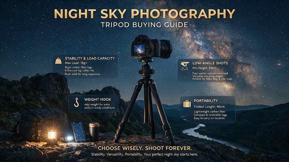
A tripod for night sky photography should be selected by stability, complete system load, working height, head security, terrain, wind exposure, and realistic carry weight rather than payload alone. This guide explains the difference between safely holding equipment and remaining steady during long exposures. It compares carbon fiber and aluminum, three-, four-, and five-section legs, center columns, twist and flip locks, ball and geared heads, leveling bases, quick-release systems, feet, and tracker-compatible platforms. Readers receive an illustrative complete-load calculation, a seven-question decision framework, six practical use scenarios, step-by-step setup guidance, troubleshooting, environmental maintenance advice, and a detailed buying checklist. The central recommendation is to choose the lightest tripod that remains dependable with the exact camera, lens, head, tracker, wind, and ground conditions in which it will actually be used.
Light Pollution Filters for Astrophotography: Do They Really Work?
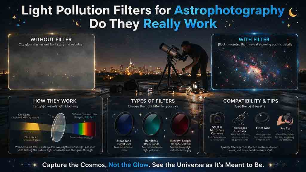
Light pollution filters can improve astrophotography, but their value depends on the target spectrum, local lighting, filter transmission curve, camera, and optical system. Dual-band and narrowband filters are most effective on emission nebulae because they isolate hydrogen-alpha, oxygen, and other narrow emission lines while rejecting much of the sky background. Broadband suppression filters offer smaller and less predictable gains on galaxies, reflection nebulae, star clusters, and Milky Way nightscapes, especially under broad-spectrum LED lighting. This guide compares filter categories, explains fast-optics passband shift, vignetting, focus changes, color casts, and halos, and provides an illustrative contrast and signal-to-noise calculation. Readers also receive a seven-question decision framework, matched A/B testing procedure, practical scenarios, troubleshooting, a complete buying checklist, and an essential warning that nighttime astrophotography filters are never safe solar filters.
Star Tracker vs Equatorial Mount: Which One Should You Buy?
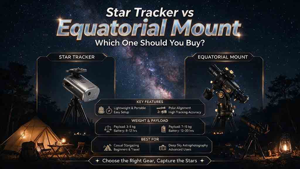
A star tracker is usually the better purchase for portable camera-lens astrophotography, while a full equatorial mount is better suited to telescopes, longer focal lengths, heavier accessories, dual-axis guiding, GoTo, plate solving, and automated imaging. This guide explains why the market also contains a middle category of dual-axis GoTo trackers, so product labels alone cannot determine the correct choice. It compares payload, torque, tracking consistency, guiding axes, periodic error, meridian behavior, transport, setup time, power, software, and complete ownership cost. Readers receive an illustrative torque calculation, a usable-integration calculation, a seven-step decision framework, six practical scenarios, troubleshooting tables, and a comprehensive buying checklist. The central recommendation is to choose the smallest system that reliably supports the real focal length, complete load, workflow, and upgrade plan.
Explore More Topics
Dedicated Astronomy Camera vs Regular Camera: What Is the Difference?
A dedicated astronomy camera is designed for telescope imaging through astronomy software and may provide regulated cooling, high-frame-rate readout, monochrome capture, filter-wheel integration, and FITS metadata. A regular DSLR or mirrorless camera is a self-contained general-purpose camera with a screen, battery, memory card, native lenses, autofocus, and daytime usefulness. This guide explains why neither category is universally better. It compares cooled deep-sky cameras, uncooled planetary cameras, guide cameras, monochrome and one-shot-color sensors, regular cameras, and specialized astrophotography DSLRs. Readers learn how cooling, dark current, H-alpha response, UV/IR filtering, sensor size, pixel scale, back focus, software, power, calibration, frame rate, and total system cost affect the decision. The article also includes calculation examples, use-case recommendations, a five-question selection process, a buying checklist, common mistakes, troubleshooting, and practical next steps.

How to Choose a Camera for Astrophotography
Choosing an astrophotography camera starts with the target, optical system, and workflow rather than megapixels or sensor size alone. This guide compares mirrorless and DSLR bodies, cooled one-shot-color cameras, cooled monochrome cameras, planetary cameras, and astronomy-modified models. Readers learn how sensor dimensions affect field of view, how pixel size and focal length determine image scale, and how cooling, quantum efficiency, read noise, full-well capacity, dynamic range, and frame rate should be interpreted. It also provides a color-versus-monochrome comparison, telescope compatibility and back-focus checks, software and driver requirements, a total-system-cost framework, five practical scenarios, troubleshooting, and a complete purchase checklist. The central recommendation is to choose the camera that fits the target, corrected image circle, mount, software, power system, processing workflow, and complete budget.
Best Focal Lengths for Milky Way Photography
For most untracked Milky Way landscapes, a 14–24mm full-frame-equivalent view offers the best balance of sky coverage, galactic scale, foreground context, and shutter-time tolerance. Wider 12–16mm views suit dramatic foregrounds and a large Milky Way arch, while 28–35mm makes the galactic center more prominent. Focal lengths of 40–50mm or longer are better for panoramas, stacking, or tracked high-detail images. This guide converts the recommendations for full-frame, 1.5× APS-C, 1.6× Canon APS-C, and Micro Four Thirds cameras. It explains shutter-time tradeoffs, crop-factor calculations, aperture and corner-performance limits, prime-versus-zoom choices, panorama planning, and tracker use. Readers also receive a three-question lens-selection method, real-world scenarios, a step-by-step lens test, a buying checklist, common mistakes, troubleshooting guidance, and practical recommendations without unsupported “best lens” claims.